Courses: Introduction to GoldSim:
Unit 14 - Modeling Scenarios
Lesson 8 - Changing Model Logic, Time Series and Other Inputs Between Scenarios
In the previous Lessons, we explained that different scenarios within a model are specifically differentiated by having different values for one or more Data elements. These elements are referred to as Scenario Data.
This means that the only elements that can differ between scenarios in a model are Data elements. Your first reaction to this might be that this is very limiting. Yes, this allows you to change simple input values, but what if you wanted differentiate scenarios in a more complex way, such as having different scenarios use different time series inputs, or even completely different logic for some parts of the model?
If you think carefully about this, however, you should realize that by changing the values for Data elements, you can do any of these things. To illustrate this, we will consider three examples:
- Scenarios that use different Lookup Tables;
- Scenarios that use different Time Series; and
- Scenarios that use different logic for a particular calculation.
These are best illustrated by considering a very simple Example. The model can be found in the “Examples” subfolder of the “Basic GoldSim Course” folder you should have downloaded and unzipped to your Desktop. In that folder, open a model file named Example27_Complex_Scenarios.gsm.
The model looks like this:
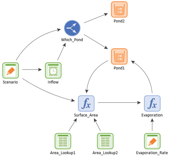
This is a model of a pond with an inflow rate (represented by a Time Series) and an evaporation rate.
If you look at the Scenario Manager (F7), you will see that there are three scenarios defined (Wet, Normal and Dry). If you look at the Scenario Data dialog, you will note that there are two Scenario Data elements:
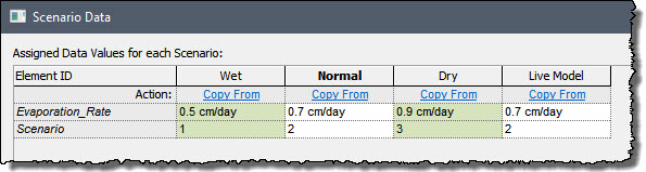
Evaporation_Rate is simply being used in the same manner it was used in our previous Example: the evaporation rate is assumed to have a different value (in cm/day) for each scenario. The other Scenario Data element (named Scenario), however, is being used in a different way to control other parts of the model. This element simply takes on a different integer value for each scenario (1, 2 or 3).
Let’s look at the model again to see how this Scenario Data element is being used. First, let’s note that there are two different Lookup Tables in this model. The Lookup Tables are being used to convert a water volume to a surface area. If we look at the Surface_Area element, what we see is that the Scenario Data element is being used to determine which Lookup Table should be used:
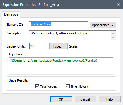
As can be seen, if the Scenario Data element has a value of 1 (corresponding to the “Wet” Scenario), one Lookup Table is used. If it has any other value (i.e., corresponding to the “Normal” or “Dry” Scenario), the other Lookup Table is used. Hence, the Scenario Data element named Scenario is used as a “flag” to determine which Lookup Table is to be used.
We can do something similar with Time Series. However, in this case, we don’t need to create multiple Time Series elements, as Time Series elements actually have the ability to store multiple data sets.
Double-click on the Inflow Time Series:
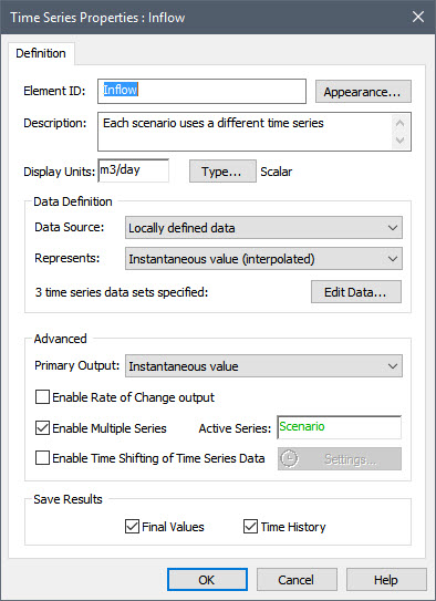
As you can see, Time Series have an advanced option to Enable Multiple Series. Press the Edit Data button to view the three time series that have been defined:
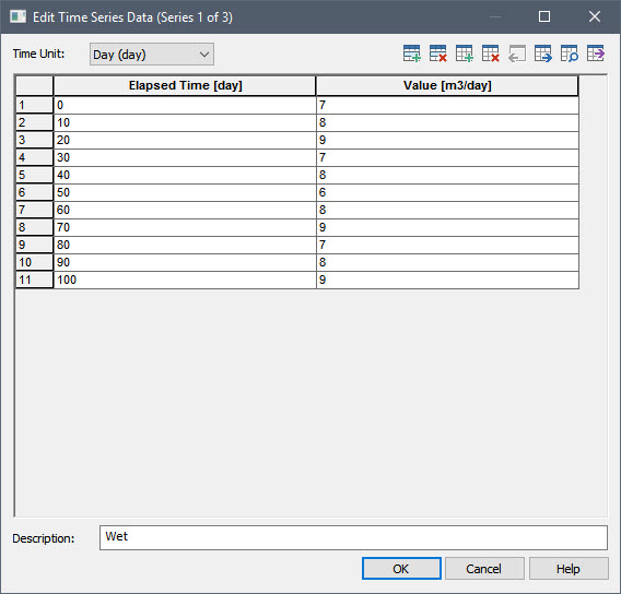
When multiple series are enabled, several buttons are added to the top of the dialog to allow you to add, delete and move between series. In this case, there are three series defined. The third button from the right moves forward (to look at the next series), and the fourth button from the right moves backward (to look at the previous series). Use those buttons now to look at the other two series.
Obviously, in any given simulation, only one time series can be used. This is the Active Series (an integer). In this model, the Scenario Element named Scenario determines the Active Series (1, 2 or 3). For example, if Scenario = 2, then the Active Series for the simulation would be the second of the three series. This allows the Scenario Data element named Scenario to be used as a “flag” to determine which time series is to be used.
Finally, open the Splitter element named Which_Pond:
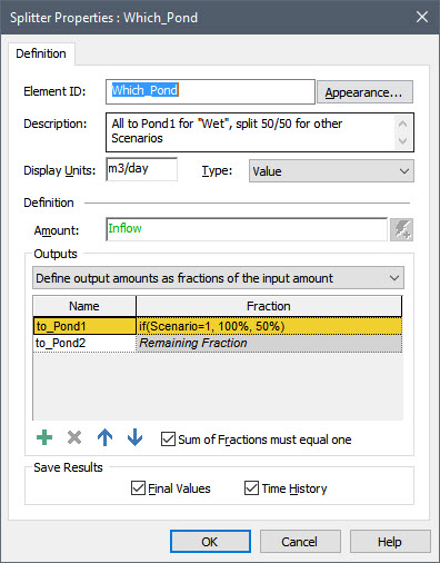
In this example, we see that the Scenario Data element is used to modify the logic in the model. In particular, if Scenario =1 (corresponding to the “Wet” scenario), all the water flows to Pond1. If it takes on any other value, half flows to Pond1 and half flows to Pond 2.
This simple example model illustrates how you can use Scenario Data elements to differentiate scenarios in complex ways, such as having different scenarios use different time series inputs, different Lookup Tables, or even completely different logic for some parts of the model.
Note: GoldSim also supports an advanced feature called conditional Containers. These provide a powerful way to represent different conceptual model logic between scenarios. These will be mentioned briefly in Unit 17, but are beyond the scope of this Course. Briefly, conditional Containers can be turned “on” or “off” using triggers. This allows you, for example, to create multiple parallel Containers that could represent different conceptual models. A Scenario Data element could then be used to trigger which Container was used for a particular simulation (e.g., one Container would be “on” for a particular scenario, while others would be “off”).