Courses: Introduction to GoldSim:
Unit 5 - Understanding and Working with Elements
Lesson 2 - Creating Elements
In the previous Unit we learned how to insert an element. In this Lesson, we are going to discuss the process of creating elements in a bit more detail.
As you recall, one way to create an element is to use the context menu that appears when you right-click in the graphics pane:
- Right-click in the graphics pane in the approximate location where you want to place the element. A context menu will appear.
- Now place your cursor over “Insert Element” and another sub-dialog will appear. In that sub-dialog, you then place your cursor over one of the categories (e.g., “Inputs”), and the menu will expand further:
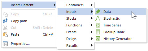
- Finally, left-click on the element type of interest (e.g., “Data”). This will insert that type of element (at the cursor location from where you originally right-clicked) and immediately display the dialog for that element.
To assist with this discussion, insert a Data element now. The top part of the dialog will look like this:
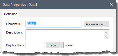
Almost all element types share some fundamental features (and hence the top of their dialogs will look identical to this).
Note that GoldSim assigns a default name to the element consisting of the element type, followed by a number (e.g., Data1). Moreover, when the element is inserted, this Element ID is selected. This makes it easy for you to immediately start typing to change its name (and you always should). All elements should be given descriptive, useful names. Naming something “X” or “A1” is not helpful to anyone viewing the model!
Element names can be fairly long (up to 30 characters), and as you will learn in subsequent Lessons, you never need to actually type in the name of an element anywhere like we did in the previous Lesson. GoldSim provides other tools to insert and reference element names in an easy way, so using long, descriptive names is rarely a problem. The following rules, however, apply to element names:
- They can only include letters, numbers and the underscore (“_”) character.
- They cannot include spaces.
- They cannot begin with a number.
In addition, you will find that some names (e.g., sin, cos, Year) are reserved for use by GoldSim. If you try to use these as element names, GoldSim will prevent this.
Note: Two types of elements that we will discuss in subsequent Units (Result elements and Dashboards) have a bit more flexibility in terms of their names. In particular, their names can include spaces.
By default, all element names must be unique. If you tried to create two elements with the same name, GoldSim would prevent you from doing so. This is because at some point you may need to reference the name in another element. If two elements had the same name, it would be ambiguous as to which element was being referenced.
Having said that, if indeed all element names were required to be unique in a GoldSim model, it would be very difficult and cumbersome to build large, complex models. All advanced programming languages provide an ability to create local variables (such that a variable can only be referenced within a specified scope or region of the model), and hence GoldSim provides such a capability. By creating local variables, you can build models which have elements with non-unique names. We will discuss this GoldSim feature in a later Unit. Until then, however, we will assume that all of the elements we create will have unique names (i.e., they are “global” variables as opposed to local variables).
Note: Names are NOT case-sensitive, so that “a” and “A” would not be considered unique names. Note, however, that although GoldSim would not differentiate between “a” and “A”, when you reference a name in the input field for another element, GoldSim will always display it using the case in which it was defined. As a result, when naming elements, you can use capitalization to make the names more readable when they are referenced (e.g., FlowRate).
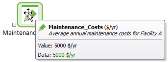
After naming your element, you should always immediately take a moment to add a Description. The Description simply provides one (of several) mechanisms for you to properly document your model. The Description is displayed in the tool-tip that is shown when you place your cursor over an element (in both the graphics pane and the browser):
The Appearance… button to the right of the Element ID allows you to change the appearance of the element (e.g., change colors, font, or even change the image itself). For now, we won’t worry about this. We will discuss these options in Unit 16.
The final (and most critical) items that must be defined when first creating an element are its Display Units and Type. These two items are discussed in the next two Lessons.
Note: You can close and save all the changes you have made to an element by pressing the OK button. If you press the Cancel button it will not save the changes. Recall that to edit an existing element, simply double-click on it in the graphics pane.