Courses: Introduction to GoldSim:
Unit 6 - Carrying Out a Dynamic Simulation
Lesson 10 - Representing Complex If-Then Logic
As we discussed in Unit 4, “If-then” statements are part of all programming languages, and as GoldSim can be thought of as a high-level programming language, it also supports this functionality. “If-then” statements have three parts:
- A condition/question (which is either True/Yes or False/No);
- The result if the condition/question is True/Yes; and
- The result if the condition/question is False/No.
For example, you may recall that we built an if-then statement that set a variable to zero after a specified simulation time:
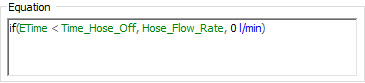
The If function is one of the built-in functions provided by GoldSim. The first argument must be a condition, the second is the result if the condition is True, and the third is the result if the condition is False.
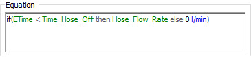
To make such statements more readable, GoldSim provides an option for the If function: you can replace the commas between the arguments with “then” and “else”:
In many models, what you actually have is more complex if-then logic. For example, imagine you needed to implement this logic:
If A < B, the answer is X,
If A >= B and A < C, the answer is Y
If A >= C, the answer is Z
Such logic can be implemented using an If statement in GoldSim, and would look like this (if you want to try it yourself simply create dimensionless Data elements for A, B, C, X, Y and Z, and then create this Expression):
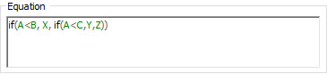
Effectively, we have nested one If statement inside another. The problem with such a statement is that it is difficult to read. Moreover, imagine that instead of having three possible results (X, Y, Z), there were five or six. The statement would become exponentially more unreadable!
Yet, such logic is often required for complex models. Hence, to facilitate representing such logic, GoldSim has a specialized element called a Selector. That is, the purpose of a Selector is to implement complex if-then logic.
Insert a Selector now (you will find it under the “Functions” category). The dialog looks like this:
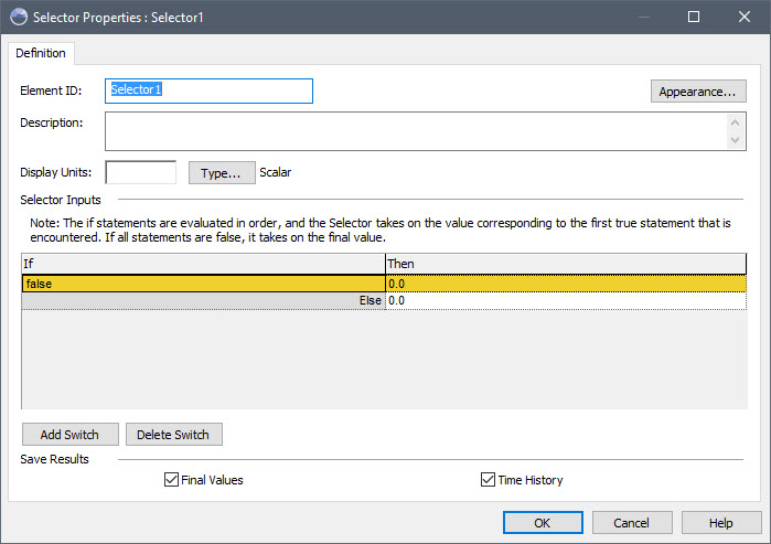
By default, there is a single condition (in the “If” column), a result if True (“Then” column), and a result if False (next to the “Else”). You can add additional switches using the Add Switch button.
Note: The Selector dialog is wider than that for other elements to allow for long “if” and “then” expressions without wrapping, hence making these easier to read.
Here is what the logic we implemented above would look like in a Selector (again, try it yourself):
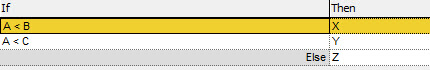
Note that this is much easier to read and understand than using an If function in an expression.
A couple points should be noted regarding the use of Selectors:
- Everything in the “If” column must be a condition.
- It is possible (and in fact likely) that multiple conditions in the “If” column will be True. If multiple conditions are True, the result is that which is associated with the first True condition in the list.
Recall that in an earlier Unit, we pointed out that outputs could be specified as being conditions for many elements (and in fact, as we shall see, for some elements they are always conditions). Doing so can make much of the logic in your model easier to understand.
For example, in the logic we implemented above, we could define an Expression element as follows:
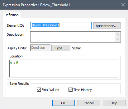
In this example, the Expression is defined as a condition (A < B). If we created an analogous Expression for A < C, we could rewrite the Selector to look like this:
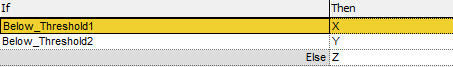
Now you see the advantage of creating elements that are conditions (rather than just writing conditional expressions). It is much more readable.
There is another advantage to creating elements whose outputs are conditions. The simple model above would look something like this in the graphics pane:
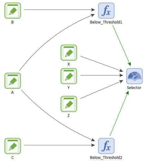
Note that the influences from the two conditional Expressions to the Selector are green (as opposed to black). This is because the colors of influences can be controlled such that they reflect the type of information being passed. By default, conditions are green, and values are black. We’ll explore this a bit more in a subsequent Unit. The key point, however, is that because the influences tell you something about the information being passed, simply glancing at the model in the graphics pane can provide useful information about your system.
Finally, it should be mentioned that conditional expressions can be complex, and include the And, Or or Not operators. For example,
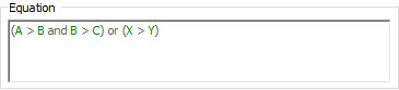
This condition evaluates to True if:
- X > Y ; or
- A > B and B > C
Of course, building complex conditional expressions like this can also make it hard to understand a model. To address this, GoldSim provides three logical elements (And, Or and Not), whose output is always a condition. For example, this is an And element (found in the “Functions” category)
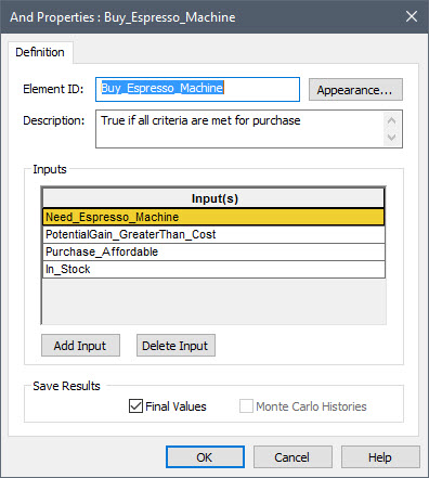
All inputs must be True for the output to be True.
This allows you to create logic diagrams in your models:
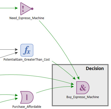
Alternatively, this same logic could be implemented more concisely in a Logic Tree element:
