Courses: Introduction to GoldSim:
Unit 7 - Modeling Material Flows
Lesson 2 - Adding an Upper Bound to a Reservoir
In the previous Unit, we built a simple model using a Reservoir element. Recall that mathematically, what a Reservoir does is integrate its inflows and outflows with respect to time in order to compute its value at any time τ in the future:
\(\displaystyle \mathrm{Value(\tau)=Initial \ Value+\int_0^{\tau}(Additions - Withdrawals)dt}\)
Let’s open the model we built in the last Exercise to look at the Reservoir element again. You should have saved that model and named it Exercise3.gsm. Open the model now. (If you failed to save that model, you can find the Exercise, named Exercise3_Selector_Runoff.gsm, in the “Exercises” subfolder of the “Basic GoldSim Course” folder you should have downloaded and unzipped to your Desktop.)
Double-click on the Reservoir element. It should look like this:
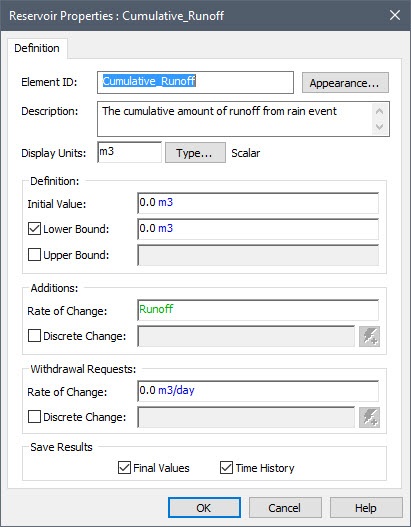
Note that the Reservoir has a number of inputs that we are not currently using. One of these is the Upper Bound. Click the check box next to that input field to activate it. Enter 100000 m3 into the field. Now run the model. When you do so, GoldSim will display a warning message:
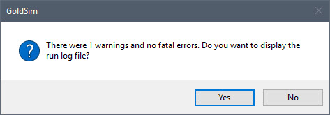
We will revisit this message in the next Lesson. For now, press No to close the message. Now plot the time history for the Reservoir. You will see that the Reservoir reaches a volume of 100,000 m3 at 13 days, and then is held constant at that value for the remainder of the simulation.
So what is happening here? Since we told GoldSim that the Reservoir had an Upper Bound of 100,000 m3, GoldSim is clearly respecting that and not allowing the volume to exceed that value. But what is happening to the water that is flowing into the Reservoir after that Upper Bound is reached? To answer that question, we need to take a step back and discuss element outputs again.
The elements we have looked at in detail so far (Data, Expression, and Selector) had a single output. However, many elements in GoldSim actually have multiple outputs. The Reservoir is one such element. Although we did not notice this when we first used a Reservoir, it always has at least two outputs (for some elements, such as the Reservoir, the number of outputs change depending on how the input options are specified). In particular, by default, a Reservoir has two outputs. However, if a Reservoir is assigned an Upper Bound, it has four outputs.
How can we see these other outputs? As noted previously, GoldSim elements have two small boxes (that are sometimes hidden) surrounding each symbol (one on the left and one on the right). These are referred to as ports. The port on the right is the output port. If an element has saved results, the output port is visible (and green) in Result Mode. Left-click on the output port for the Reservoir:
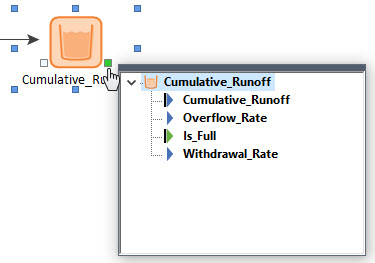
When you left-click on the output port for an element, it displays an output interface that shows all of the element’s outputs (indented under the element name). For the Reservoir in this example, what you will note here is that there is one output that has the same name as the element itself, and then three additional outputs. The output with the same name as the element is referred to as the primary output. The other outputs are referred to as secondary outputs.
What is important to understand is that when we reference another element’s name in an input field, we are not really referencing the name of the element at all; we are referencing the name of the element’s primary output. For elements that have a single output (e.g., Data, Expression), that single output is, of course, the primary output. A primary output represents the key output (i.e., the output that you are likely most interested in). For a Reservoir, this is obviously the current value of the integral. As we shall see, however, for some elements with multiple outputs, there is no reason to think one output is more important than another. In those cases, all of the outputs are secondary outputs (i.e., not all elements have a primary output).
So how do we reference a secondary output in an input field? If you look at the outputs for the Reservoir above, you will note that there is a secondary output named Overflow_Rate. Can we simply reference that? The answer is no. Why? Because every Reservoir with an upper bound has an output named Overflow_Rate. If we just referenced that name, and we had multiple Reservoirs with upper bounds, GoldSim would have no way to know which Reservoir was being referenced. To avoid this problem, to reference a secondary output, you need to reference both the element name and the output name as follows: ElementID.OutputID. Hence, the Overflow_Rate output from a Reservoir named Cumulative_Runoff would be referenced as:
Cumulative_Runoff.Overflow_Rate
For primary outputs, the OutputID is the same as the ElementID. Since they are identical, however, it is not necessary to specify both when referencing the primary output (e.g., Reservoir1.Reservoir1).
As is the case for primary outputs, you never have to type the full name of the output into a field, as GoldSim provides tools to help with this. For example, when right-clicking in an input field to link to an output, you can expand the element and select a specific output:

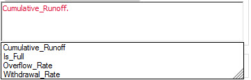
Similarly, if you enter the name of an element in an input field, followed by a period (.), GoldSim will display the various outputs you can select from as suggestions, and clicking one of these inserts it:
There is another way to see all the outputs (and inputs) for an element. If you right-click in the browser, a context-menu will appear:

If you select Show Element Subitems, you will be able to expand all the elements in the browser to see their inputs and outputs:
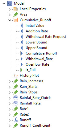
Note: You may have noticed above that icons representing inputs and outputs vary from item to item. Inputs have triangles pointing to the left; outputs have triangles pointing to the right. A green triangle indicates that the input/output is a condition. A dot on at the point of a triangle indicates that the input/output is linked to another element. A solid black line to the left of a triangle on an output indicates it is a special type of output (a state variable), which we will discuss in a subsequent Unit. And finally, in Result Mode, outputs for which results were saved will have their names highlighted in bold.
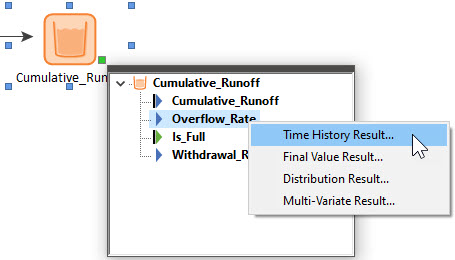
Now that we have discussed secondary outputs, we can return to the overflowing Reservoir issue we started to examine at the beginning of this Lesson. Recall that when we specified an Upper Bound, GoldSim respected that and held the volume at that value once it reached it. But what is happening to all of the water that is flowing into the Reservoir? It is “overflowing”. And we can see that by plotting the Overflow_Rate output. To plot a primary output, all we need to do is right-click on the element itself and select Time History Result… But to plot a secondary output, we need to open the output interface (by left-clicking on the output port) and right-click on the output of interest:
If you do this for the simple example we set up earlier in this Lesson, you will see that the Reservoir started overflowing at 13 days, and stopped overflowing at 20 days (when the Runoff went to zero):
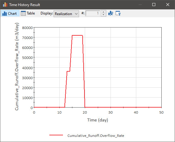
Note: When you define an Upper Bound for a Reservoir, it adds two outputs to the element: the Overflow_Rate and another output named Is_Full. The Is_Full output is a condition. The Is_Full output is True when the Reservoir is at the Upper Bound, and False otherwise.
Finally, you will recall that when we ran this model, there was a warning message. This warning message was related to the fact that the Reservoir was overflowing. We will revisit this in the Exercise we will work on in the next Lesson.
We will look at this model again in a future Unit, so before closing it, let’s remove the Upper Bound:
- Return to Edit Mode (e.g., by pressing F4).
- Open the Reservoir element.
- Clear the Upper Bound check box.
- Close the dialog and save the file.