Courses: Introduction to GoldSim:
Unit 15 - Modeling Scenarios
Lesson 3 - Creating Scenarios
In this Lesson, we will start with the same model we looked at in the previous Lesson, but before any of the scenario modeling features have been added. Then over the next several Lessons we will walk through and discuss in detail how to create, define, run and compare scenarios. In this Lesson, we will first discuss how to create scenarios.
We will start with another Example model that can be found in the “Examples” subfolder of the “Basic GoldSim Course” folder you should have downloaded and unzipped to your Desktop. In that folder, open a model file named Example31_Adding_Scenarios.gsm.
This model is identical to the model we discussed in the previous Lesson, with the exception that it has no scenarios defined (and hence no scenario features enabled).
Let’s start by adding some scenarios. We will do so by using the Scenario Manager. The Scenario Manager can be accessed from the main menu (Run|Scenario Manager…) or by pressing F7. There is also a toolbar button for the Scenario Manager:

Open the Scenario Manager for the model now:
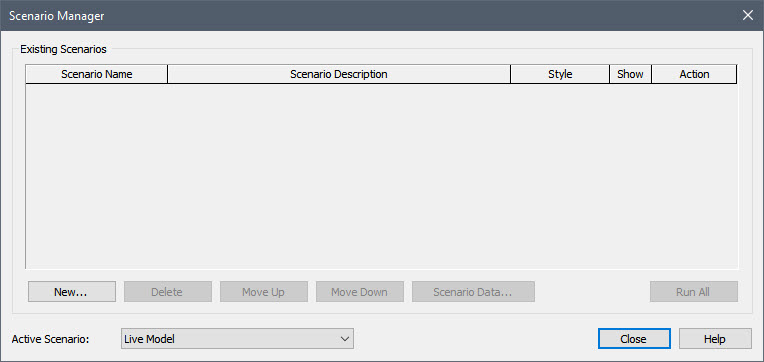
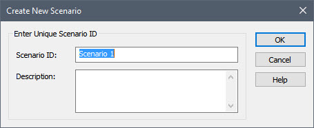
By default, a model has no scenarios defined. To activate GoldSim’s scenario modeling features, we need to add one or more scenarios. You can add a scenario by pressing the New… button. When you do so, you are prompted for a Scenario ID and Description:
Add three scenarios so that the Scenario Manager looks like this:
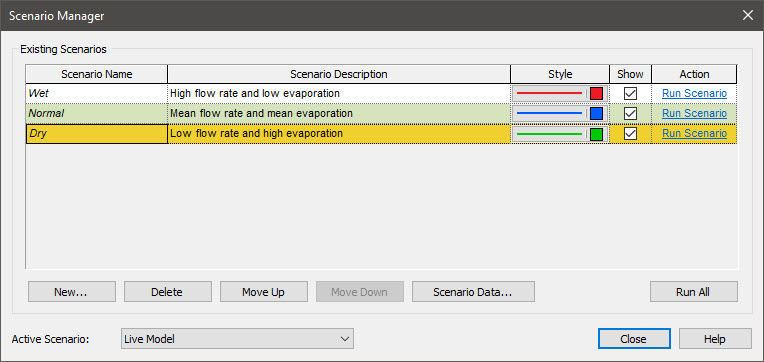
After creating a scenario, you can edit its Name and/or Description by simply clicking in the field.
Now that we have created the scenarios, we next need to define the Data elements that differentiate the scenarios. That is, we need to specify which of the Data elements are Scenario Data, and define values for those for each scenario.
First, we will specify which Data elements are Scenario Data. There are two ways to do this. Let’s illustrate both. The first way is to press the Scenario Data… button from within the Scenario Manager:
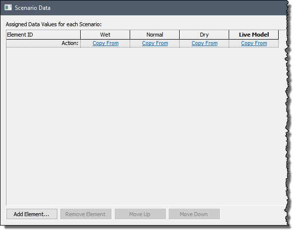
Press the Add Element… button and a browser window (showing only Data elements) will be displayed. Select Evaporation_Rate and press OK. That element will be added to the Scenario Data list:
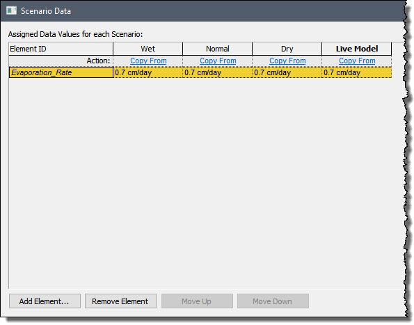
(Don’t worry about the values for the various scenarios – they are all identical for now. We will specify those values below.)
Now let’s specify another Data element as Scenario Data using another method. Close the Scenario Data and Scenario Manager dialogs. Now double-click on the Mean_Inflow Data element:
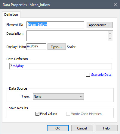
What you should notice here is that once you have defined at least one scenario in your model, the dialog for Data elements is modified slightly. Specifically, the dialog provides an option to define a Data element as a Scenario Data element. This has not yet been defined as being Scenario Data (and hence it has the same value for all Scenarios). As can be seen, a Scenario Data checkbox is available (and in this case, unchecked). Check the Scenario Data box now, and the following dialog will be displayed:
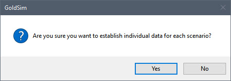
Select Yes and this element will be added to the list of Scenario Data elements. You will note that once a Data element is defined as being Scenario Data, the dialog changes again:
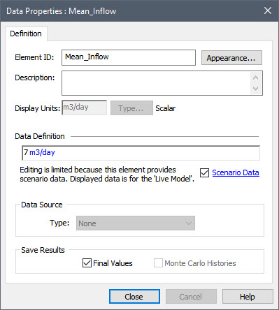
It indicates that editing is “limited”. In particular, you will note that some of the editing is locked (e.g., you cannot change the Type or dimensions), and although you can change the value (i.e., the Data Definition field), you cannot enter links (entries must be values, expressions containing only values, or, if the Data is a Condition, True or False). We will discuss editing the value for Scenario Data elements in the next Lesson.
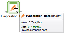
Note also that the icon for the element has changed (the pencil is orange), and if you hold your cursor over a Scenario Data element, it indicates that it provides scenario data:
Now that we have specified which Data elements are Scenario Data, let’s return to the Scenario Data dialog (F7, then press Scenario Data…) to define the values to use for each scenario. The dialog will look like this:
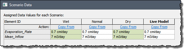
As you can see, the values are the same for all scenarios (they are the values that were defined before any scenarios were added). So this is obviously not very interesting, as all three scenarios are identical. Change the values for the “Wet” and “Dry” scenarios as follows:
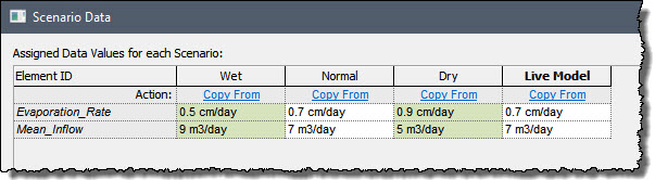
You can ignore the “Live Model” column for now (leave it as it is). We will discuss that in the next Lesson.
Note: You may have noticed that the Scenario Data are listed in a different order here than they were when we looked at the completed model in the previous Lesson (the order is based on the order they were added). The order they are listed has no effect and is purely cosmetic. Note, however, that you can change the order by using the Move Up and Move Down buttons.
We have now made all the changes to the model required to create and compare scenarios. We will spend the next several Lessons exploring how the scenario modeling features work. We will continue to explore this model in the next Lesson, so you should now close the Scenario Data and Scenario Manager dialogs and save the model (as Adding_Scenarios.gsm) to the “MyModels” subfolder in the “GoldSim Course” folder on your desktop.